PROTEGO®
Deflagration Flame Arresters, in-line
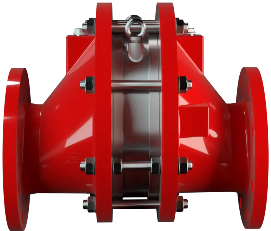
Stopping Deflagrations in Pipelines
PROTEGO® Deflagration Flame Arresters Arrête-flammes antidéflagration Flame arrester designed to prevent the transmission of a deflagration. It can be an end-of-line flame arrester or an in-line flame arrester. are installed in pipelines and on process equipment to suppress deflagrations in systems handling explosive mixtures.
Designed for the up and downstream oil and gas, petroleum, chemical, pharmaceutical, offshore, marine and bio-energy industries, the range covers a wide variety of types, designs, sizes, and materials, with customized solutions for non-standard substances and applications.
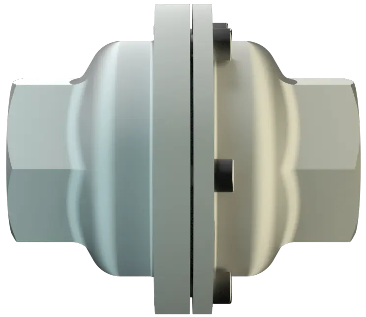
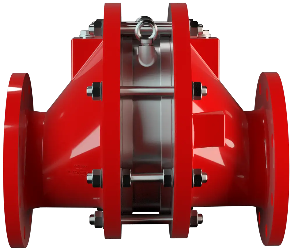
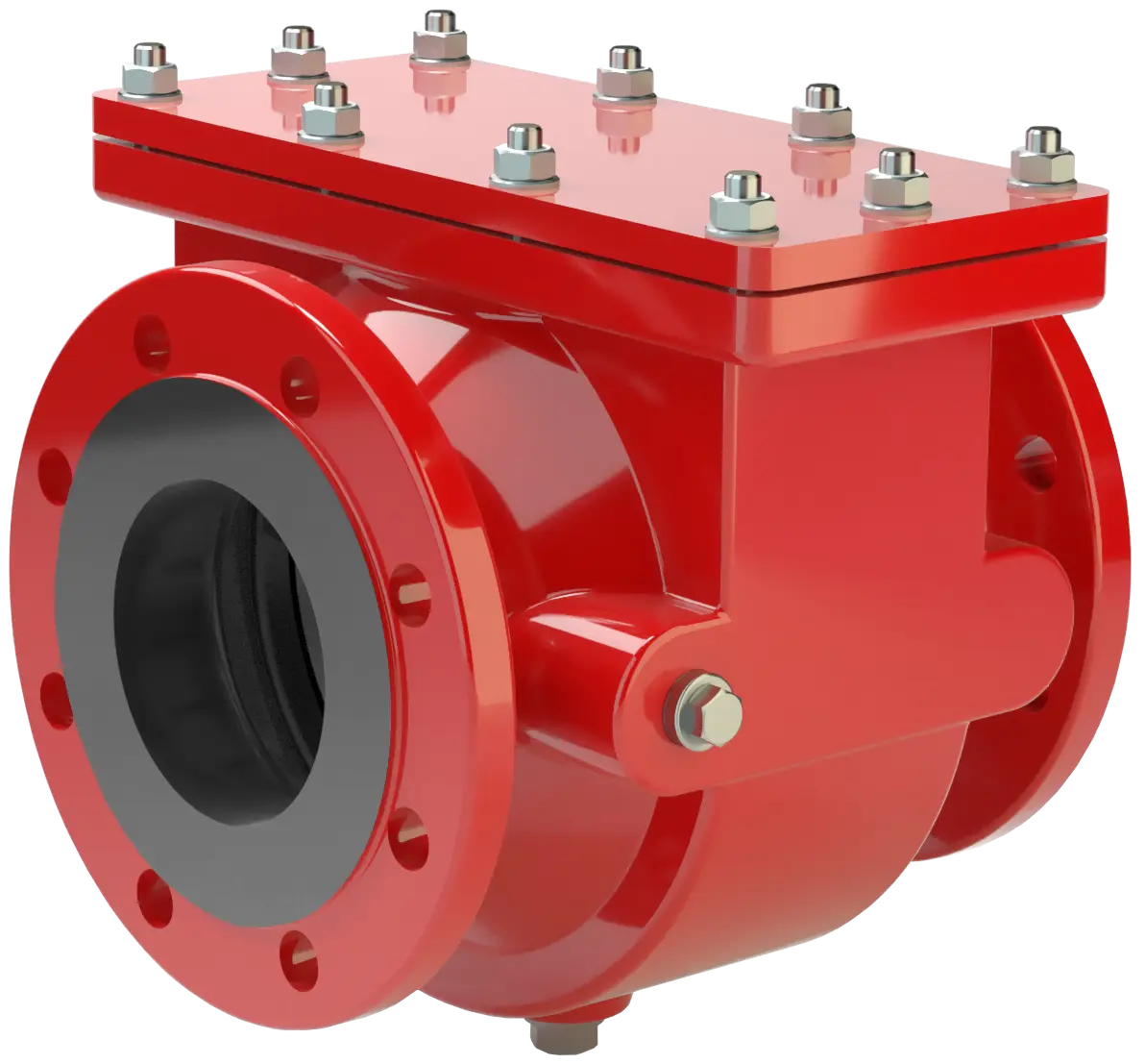
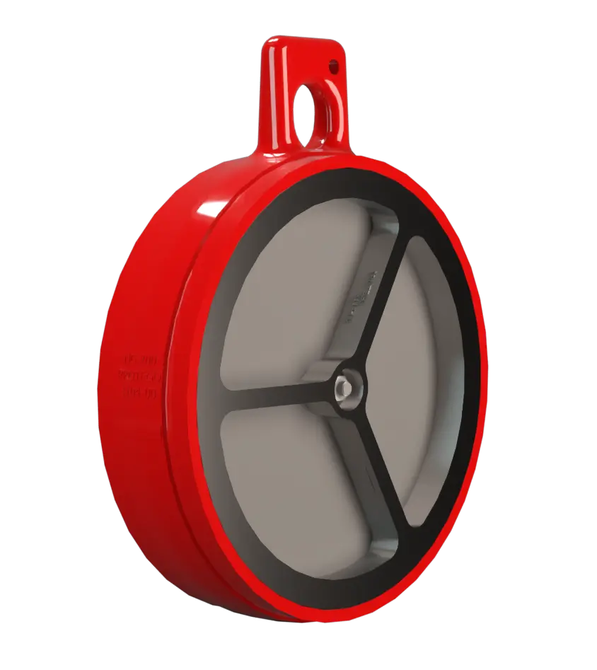

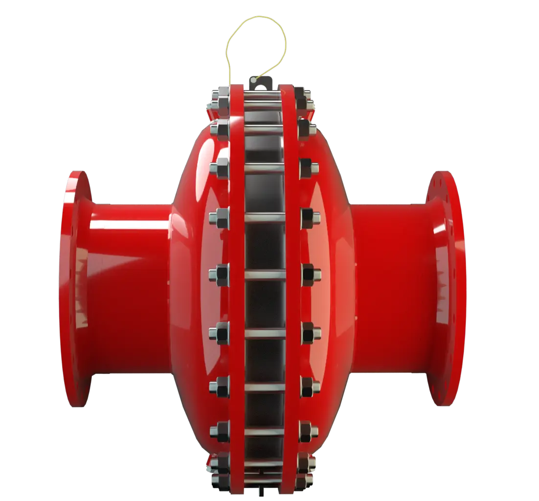
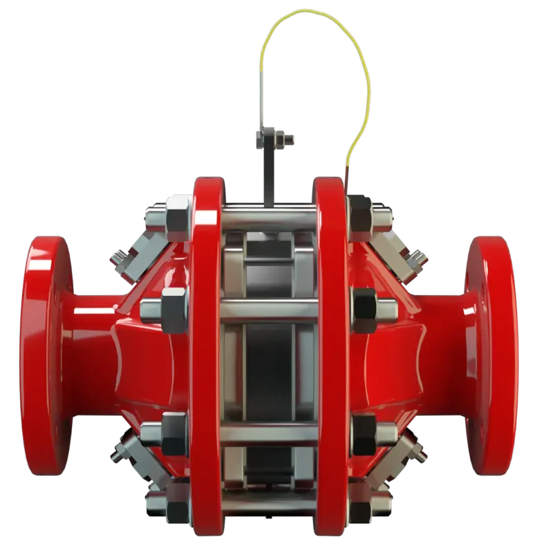
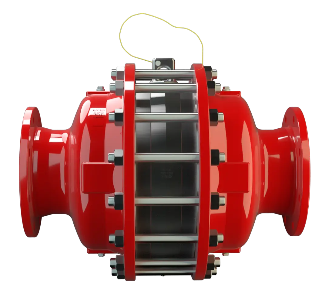
Highlights of PROTEGO® Deflagration Flame Arresters
Product Overview
Deflagration vs. Detonation
A deflagration is a flame front that travels through an explosive mixture at subsonic speed. In a pipeline, that flame front carries enough energy to destroy process equipment that was not designed to withstand explosion pressure. The function of the Deflagration Flame Arrester is to intercept and extinguish that flame before it reaches the equipment you are protecting.
Flame Arrester Unit
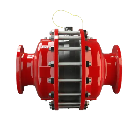
PROTEGO® Deflagration Flame Arresters accomplish this through a proprietary Flame Arrester Unit consisting of FLAMEFILTER® discs housed in a FLAMEFILTER® casing. The discs create a network of precise narrow gaps that extract thermal energy from the deflagration faster than the flame can sustain itself, extinguishing it at the element.

Available Options
We are highly impressed to see the quality of the products and the knowledge to help us build a state-of-the-art storage terminal. We have always appreciated the timely deliveries of the flame arresters and other equipment.
Typical Applications for PROTEGO® Deflagration Flame Arresters
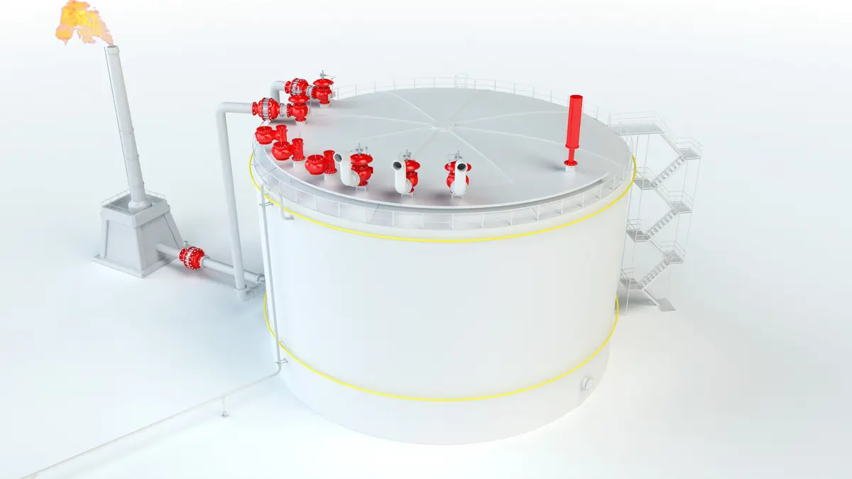
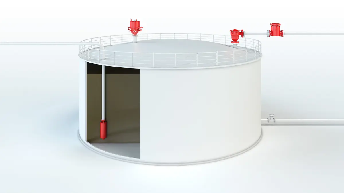
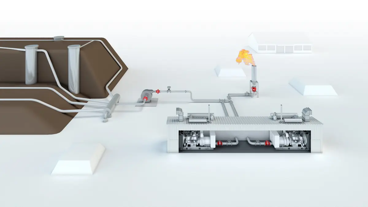
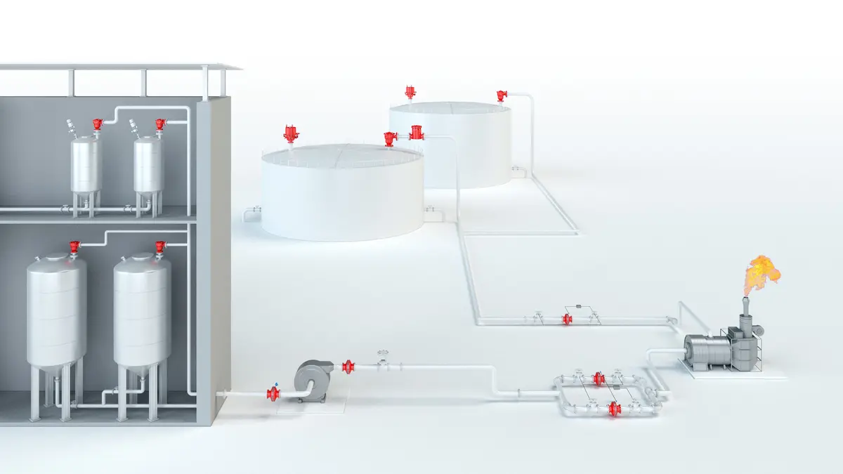
We provide engineered safety solutions.
Since 1954, PROTEGO® has built and provided Flame Arresters, Pressure and Vacuum Relief Valves Soupape de surpression et dépression A pressure and vacuum relief valve is a pressure equalization valve for impermissible pressure and vacuum in a closed system. and Tank Equipment, now with the help of more than 750 employees worldwide.

How It Works
When a flame front enters the arrester, it passes through the FLAMEFILTER® discs. The narrow gaps create a large heat transfer surface, removing energy from the flame faster than combustion can be sustained. The flame is extinguished within the element.
Element Design
The design of the element is not fixed. It is selected based on:
- Explosion Explosion Réaction brusque d’oxydation ou de décomposition entraînant une élévation de température, de pression ou des deux simultanément. group of the gas or vapour
- Operating pressure and temperature
- Composition of the process medium
This ensures the device Appareil A device is a pipe component that influences the media flow by opening, closing, or partially shutting off the flow channel or by dividing or mixing the media flow. is matched to the specific risk profile of the application.
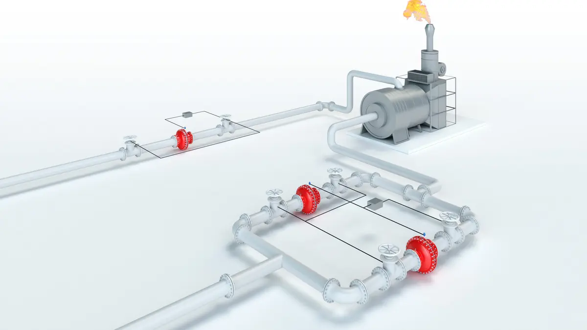
For in-line installations, it is important to understand that protection is time-limited. If an ignitable mixture continues to flow after a flame is stopped, a fire can develop on the arrester itself. For this reason, systems must include:
- Temperature monitoring at the arrester
- A defined response, such as nitrogen purging
OEM-integrated Flame Arresters are tested and approved as part of the original equipment assembly and are not used as standalone devices.
Key Features and Design Characteristics
The element can be removed and serviced without replacing the entire unit, reducing maintenance cost, effort and downtime.
Available in concentric, eccentric, and easy-access designs. Easy-access versions allow maintenance without disconnecting pipework- important in space-constrained or high-uptime environments.
Element gap size is optimized for the gas classification (MESG). Correct selection is critical to ensure effective flame arresting.
Options are available depending on whether flow direction is fixed or variable.
Designs are available for substances that may polymerise or crystallise, helping maintain long-term performance.
Heating jackets or coils can be added where condensation or solidification is a risk.
Where standard devices are not suitable, PROTEGO® can design and certify application-specific solutions.
Engineering and Compliance
PROTEGO® Deflagration Flame Arresters are type-tested and certified according to ATEX and other international standards. Each device is supplied with a statement of conformity defining its approved operating conditions.
Additional installation considerations include:
Custom approvals can be developed for specific regulatory or operating requirements.
Sizing is based on the relationship between flow rate and pressure drop using the p/V performance diagram.
Where there is a risk of clogging, a safety factor must be applied. For non-standard applications, technical data should be submitted during specification.