Features
Function and Description
Flame Arrester Venting and Exhausting of Pipelines and Equipment
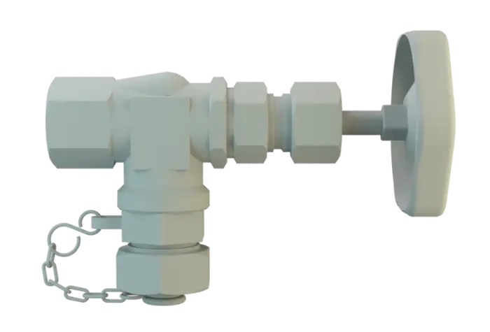
The PROTEGO® sampling and air bleed valve Soupape de distribution et de purge A deflagration-proof sampling and air bleed valve can be used both for manual venting of system components and for extracting samples of flammable liquids. is used for flame transmission-proof Flame transmission-proof Characteristic of a device to avoid flashback. venting of pipelines and equipment that transports or processes flammable liquids and for taking liquid samples. The valve incorporates an end-of-line deflagration flame arrester. Should the gas/air mixtures or product vapor/air mixtures ignite during venting, the valve prevents flash back into the protected system.

Main Component – PROTEGO® Flame Arrester Unit
The Sampling and Air Bleed Valve PROTEGO® ZE/WU consists of the threaded angle valve in pressure stage PN25 (1) with hand wheel as standard design, a female threaded connection (pipe thread G½“up to G1“), and the flame arrester (2) with cover (3). Optionally, an elbow fitting (4) is available as outlet for sampling. The PROTEGO® Flame Arrester (2) consists of the Flame Arrester casing with FLAMEFILTER®. The valve opens manually with the hand wheel. For sampling, a suitable container is required.

For Explosion Group IIB
The simple and sturdy design makes it suitable for nearly all flammable liquids. This device Appareil A device is a pipe component that influences the media flow by opening, closing, or partially shutting off the flow channel or by dividing or mixing the media flow. can be installed in any position. Flame transmission protection is guaranteed against atmospheric deflagrations of gas/air mixtures or product vapor/air mixtures of explosion groups up to IIB IIB (NEC group D to C) up to an operating temperature Operating temperature Temperature reached when the equipment is operating under design conditions. of +60°C / 140°F and an absolute operating pressure Pression de service Operating pressure is the pressure existing at normal operating conditions within the system being protected. of up to 1.1 bar / 15.9 psi. EU conformity according to the currently valid ATEX directive. Approvals according to other national/international regulations on request.
Dimensions
| DN | a | b | Ø c | d | e | f |
| G½" | 40 / 1.57 | 140 / 5.51 | 70 / 2.76 | 80 / 3.15 | 96 / 3.78 | 67 / 2.64 |
| G¾" | 50 / 1.97 | 165 / 6.50 | 85 / 3.35 | 80 / 3.15 | 89 / 3.50 | 67 / 2.64 |
| G1" | 65 / 2.56 | 200 / 7.87 | 100 / 3.94 | 95 / 3.74 | 104 / 4.09 | 67 / 2.64 |
Dimensions in mm / inches
Material
| Design | A |
| Threaded angle valve | Stainless Steel |
| Elbow | Stainless Steel |
| Cover | Stainless Steel |
| FLAMEFILTER® | Stainless Steel |
The valves must be sufficiently resistant to corrosion through the gas/air mixtures or product vapour/air mixtures. This applies mailnly to the FLAMEFILTER®.
Explosion group
| MESG | Expl. Gr. (IEC / CEN) | Gas Group (NEC) |
| ≥ 0,50 mm | IIB | B |
Type of connection
| Pipe thread DIN ISO 228 T1 | DIN |
Design Types and Specifications
There are two designs available:Optionally available with fl ange connection (see fi gure)