VD/SV-AD, VD/SV-ADL
Pressure/Vacuum Relief Valve atmospheric deflagration-proof
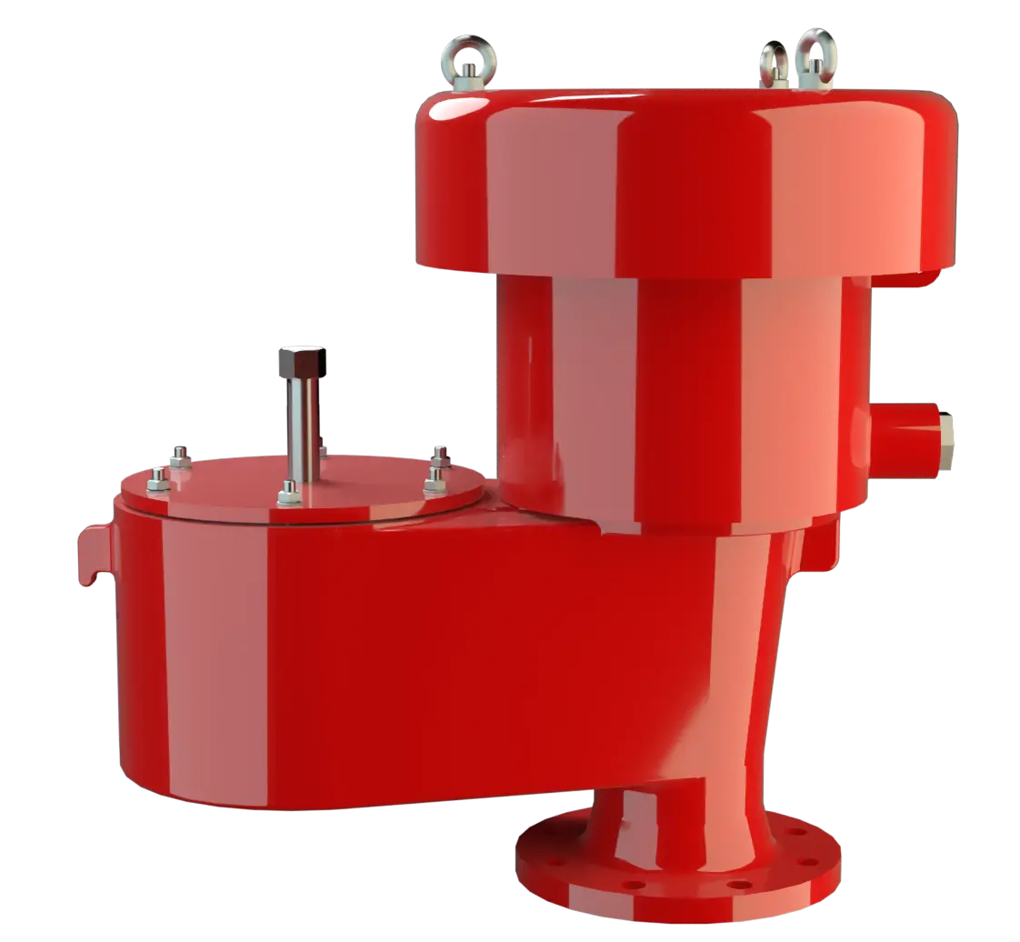
Features
Function and Description
Combined Pressure and Vacuum Relief Valve
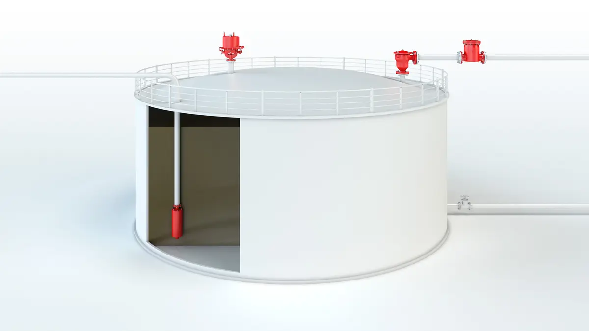
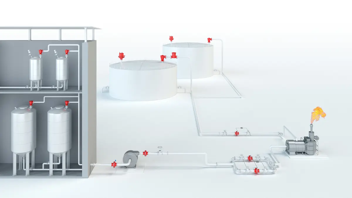
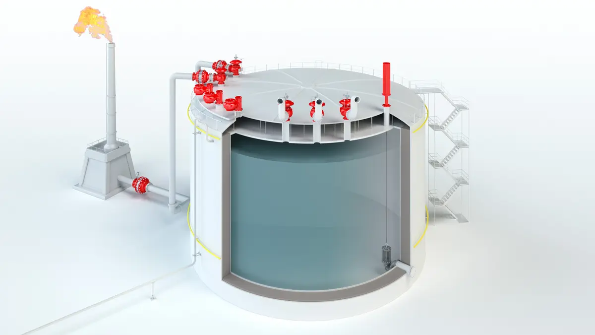
The Deflagration-Proof VD/SV-AD(L) Type PROTEGO® valve is a highly developed combined pressure/vacuum relief valve for high flow capacities with an integrated Flame Arrester Unit. It is primarily used as a device for flame-transmission-proof in-breathing and out-breathing in tanks, containers, and process equipment. The valve offers reliable protection against overpressure and vacuum, prevents out-breathing of product vapor and in-breathing of air almost up to the set pressure, and protects against atmospheric deflagration. The PROTEGO® Flame Arrester Unit is designed to achieve minimum pressure rop with maximum safety. The Deflagration-Proof PROTEGO® VD/SV-AD(L) valve is available for substances from explosion groups IIA to IIB3 (NEC group D to C MESG ≥ 0.65 mm).
10%-Technoglogy
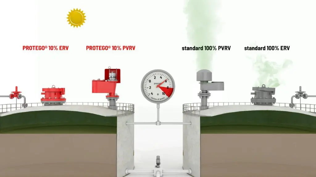
When the set pressure is reached, the valve starts to open and reaches full lift within 10% overpressure. This unique 10% technology enables a set pressure that is only 10% below the maximum allowable working pressure ( MAWP Maximal erlaubter Betriebsdruck (MAWP) Maximaler zulässiger Überdruck im oberen Bereich eines kompletten Behälters in normaler Betriebsstellung bei der genannten übereinstimmenden Temperatur, die für diesen Druck spezifiziert ist. ) or maximum allowable working vacuum (MAWV) of the tank. After years ofdevelopment, this typical opening characteristic of a safety relief valve is now also available for the low pressure range.
Advanced Manufacturing Technology
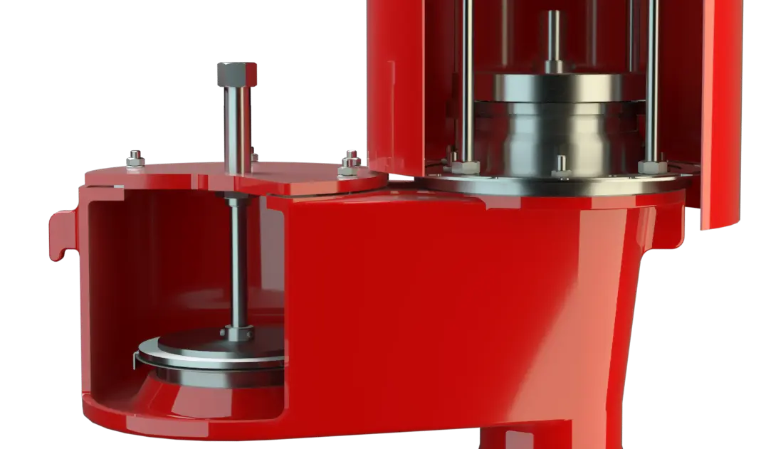
The tank pressure is maintained up to the set pressure with a tightness that is above to the normal standards due to our state-of-the-art manufacturing technology. This feature is ensured by the valve seats made of high quality stainless steel and with individually lapped valve pallets (1), or with an air cushion seal (2), in conjunction with high quality FEP diaphragm. The valve pallets are also available with a PTFE seal to prevent them from sticking when sticky substances are used and to enable the use of corrosive fluids. After the overpressure is released or the vacuum is balanced, the valve reseats and provides a tight seal.

Main Component – PROTEGO® Flame Arrester Unit
If the set pressure is exceeded, explosive gas/product vapor/air mixtures are released into the atmosphere. If this mixture ignites, the integrated PROTEGO® Flame Arrester Unit (3) revents flame transmission resulting from atmospheric deflagration into the tank. The vacuum side is also protected against atmospheric deflagration. The valve can be used at an operating temperature of up to +60°C / 140°F and meets the requirements of European Tank Design Standard EN 14015 (Appendix L) and ISO 28300 (API 2000). EU conformity according to the currently valid ATEX directive. Approvals according to other national/international regulations on request.
Dimensions
To select the nominal size (DN), please use the flow capacity charts on the following pages
| VD / SV-AD | VD / SV-ADL | |||
| DN | 80 / 3" | 100 / 4" | 100 / 4" | 150 / 6" |
| a | 540 / 21.26 | 565 / 22.24 | 650 / 25.59 | 760 / 29.92 |
| b | 475 / 18.70 | 575 / 22.64 | 700 / 27.56 | 855 / 33.66 |
| c | 350 / 13.78 | 350 / 13.78 | 600 / 23.62 | 600 / 23.62 |
Dimensions in mm / inches
Material selection for housing
| Design | A | B |
| Housing | Steel | Stainless Steel |
| Valve saets | Stainless Steel | Stainless Steel |
| Gasket | PTFE | PTFE |
| Weather hood | Stainless Steel | Stainless Steel |
| Flame arrester unit | A, B | B |
Option: Housing with ECTFE-lining
Sonderwerkstoffe auf Anfrage
Material combinations of flame arrester unit
| Ausführung | A | B |
| FLAMEFILTER® cage | Steel | Stainless Steel |
| FLAMEFILTER® | Stainless Steel | Stainless Steel |
Special materials upon request
Material selection for pressure valve pallet
| Design | A | B | C | D |
| Pressure range [mbar] [inch W.C.] | +2.0 up to +3.5 +0.8 up to +1.4 | >+3.5 up to +14 >+1.4 up to +5.6 | >+14 up to +210 >+5.6 up to +84 | >+35 up to +210 >+14 up to +84 |
| Valve pallet | Aluminium | Stainless Steel | Stainless Steel | Stainless Steel |
| Sealing | FEP | FEP | Metal to Metal | PTFE |
Special material as well as higher set pressure upon request
Material selection for vacuum valve pallet
| Design | A | B | C | D |
| Vacuum range [mbar] [inch W.C.] | -2.0 up to -3.5 -0.8 up to -1.4 | <-3.5 up to -14 <-1.4 up to -5.6 | <-14 up to -35 <-5.6 up to -14 | <-14 up to -35 <-5.6 up to -14 |
| Valve pallet | Aluminium | Stainless Steel | Stainless Steel | Stainless Steel |
| Sealing | FEP | FEP | Metal to Metal | PTFE |
Special material as well as higher set vacuum upon request
Selection of explosion group
| MESG | Expl. Gr. (IEC / CEN) | Gas Group (NEC) |
| ≥ 0,65 mm | IIB3 | C |
Special approvals upon request
Flange connection type
| EN 1092-1; Form B1 |
| ASME B16.5 CL 150 R.F. |
other types upon request
Design Types and Specifications
Any combination of vacuum and pressure levels can be set for the valveThe valve discs are weight-loaded.
There are two different designs:
Additional special devices available upon request
Settings
| Pressure: | +3.5 mbar | +35 mbar |
| +1.4 inch W.C. | +14 inch W.C. | |
| Vacuum: | -2.0 mbar | -35 mbar |
| -0.8 inch W.C. | -14 inch W.C. |
Higher and lower settings upon request
Flow Capacity Chart
The flow capacity charts have been determined with a calibrated and TÜV certified flow capacity test rig. Volume flow V in (m³/h) and CFH refer to the standard reference conditions of air ISO 6358 (20°C, 1bar). For conversion to other densities and temperatures refer to Sec. 1: “Technical Fundamentals”.