DR/EU
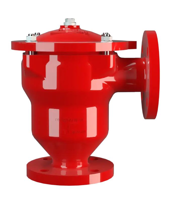
In-Line Detonation Flame Arrester for unstable and stable detonations and deflagrations in right angle design with a shock absorber, unidirectional
Features
Function and Description
Protects Against Deflagrations and Stable and Unstable Detonations
The PROTEGO® DR/EU series of in-line detonation flame arresters represents further development of PROTEGO® Flame Arrester Series DR/ES, which has been successfully used in industry for decades. The device protects against deflagrations and stable and unstable detonations. The classic right-angle design offers considerable costs and maintenance advantages over the straight-through design.

Main Component – PROTEGO® Flame Arrester Unit
Once a detonation enters the Flame Arrester, energy is absorbed from the detonation shock wave by the integrated shock absorber (1) before the flame is extinguished in the narrow gaps of the FLAMEFILTER® (3). The PROTEGO® Flame Arrester Unit (2) consists of several FLAMEFILTER® discs and spacers firmly held in the FLAMEFILTER® casing (4). The gap size and number of FLAMEFILTER® discs are by the operating conditions of the flowing mixture (explosion group, pressure, temperature). This device is can be used for explosion groups from IIA to IIB3 (NEC group D to C MESG ≥ 0.65 mm).

Many Individual Certifications
The standard design can be used with an operating temperature of up to +60°C / 140°F and an absolute operating pressure acc. to table 3. Devices with special approval for higher pressures and temperatures are available upon request. EU conformity according to the currently valid ATEX directive. Approvals according to other national/international regulations on request.
Dimensions
To select the nominal size (DN), please use the flow capacity charts on the following pages
| DN | 25 / 1" | 32 / 1¼“ | 40 / 1½“ | 50 / 2“ | 65 / 2½“ | 80 / 3" | 100 / 4" | 125 / 5" | 150 / 6" |
| a | 125 / 4.92 | 125 / 4.92 | 153 / 6.02 | 155 / 6.10 | 198 / 7.80 | 200 / 7.87 | 250 / 9.84 | 332 / 13.07 | 335 / 13.19 |
| b | 140 / 5.51 | 140 / 5.51 | 183 / 7.20 | 185 / 7.28 | 223 / 8.78 | 225 / 8.86 | 290 / 11.42 | 357 / 14.06 | 360 / 14.17 |
| c | 210 / 8.27 | 210 / 8.27 | 290 / 11.42 | 290 / 11.42 | 365 / 14.37 | 365 / 14.37 | 440 / 17.32 | 535 / 21.06 | 535 / 21.06 |
| c1 | 285 / 11.22 | 285 / 11.22 | 395 / 15.55 | 395 / 15.55 | 500 / 19.69 | 500 / 19.69 | 595 / 23.43 | 750 / 29.53 | 750 / 29.53 |
| d | 150 / 5.91 | 150 / 5.91 | 210 / 8.27 | 210 / 8.27 | 275 / 10.83 | 275 / 10.83 | 325 / 12.80 | 460 / 18.11 | 460 / 18.11 |
| e | 495 / 19.49 | 495 / 19.49 | 600 / 23.62 | 600 / 23.62 | 705 / 27.76 | 705 / 27.76 | 795 / 31.30 | 950 / 37.40 | 950 / 37.40 |
Dimensions in mm / inches
Material selection for housing
| Design | B | C | D | |
| Housing | Carbon Steel | Stainless Steel | Hastelloy | |
| Heating jacket (DR / EU-H-(T)-...) | Steel | Stainless Steel | Stainless Steel | |
| Cover with shock absorber | Steel | Stainless Steel | Hastelloy | |
| O-Ring O-Ring O-Ringe sind ringförmige Dichtung. Die Benennung leitet sich vom runden, O-förmigen Querschnitt des Rings ab. Aufgrund seines kreisrunden Querschnitts kann ein O-Ring axial und/oder radial abdichten. | FPM* | PTFE | PTFE | |
| Flame arrester unit | A | C, D | E | Special materials upon request |
* for devices exposed to elevated temperatures above 150°C / 302°F (T150), gaskets made of PTFE.
The housing and cover with the shock absorber can also be delivered in steel with an ECTFE coating.
Material combinations of flame arrester unit
| Design | A | C | D | E |
| FLAMEFILTER® cage | Steel | Stainless Steel | Stainless Steel | Hastelloy |
| FLAMEFILTER®* | Stainless Steel | Stainless Steel | Hastelloy | Hastelloy |
| Spacer | Stainless Steel | Stainless Steel | Hastelloy | Hastelloy |
* the FLAMEFILTER® are also available in the materials Tantalum, Inconel, Copper, etc. when the listed housing and cage materials are used.
Special materials upon request
Selection of explosion group
| MESG | Expl. Gr. (IEC / CEN) | Gas Group (NEC) |
| > 0,90 mm | IIA | D |
| ≥ 0,65 mm | IIB3 | C |
Special approvals upon request
Selection of max. operating pressure
| Expl. Gr. | DN | 25 / 1" | 32 / 1¼" | 40 / 1½" | 50 / 2" | 65 / 2½" | 80 / 3" | 100 / 4" | 125 / 5" | 150 / 6" |
| IIA | Pmax | 1,6 / 23.3 | 1,6 / 23.3 | 1,6 / 23.3 | 1,6 / 23.3 | 1,6 / 23,.3 | 1,6 / 23.3 | 1,5 / 21.7 | 1,2 / 17.4 | 1,2 / 17.4 |
| IIB2 | Pmax | 1,4 / 20.3 | 1,4 / 20.3 | |||||||
| IIB3 | Pmax | 1,6 / 23.2 | 1,6 / 23.3 | 1,6 / 23.3 | 1,6 / 23.3 | 1,6 / 23.3 | 1,6 / 23.3 | 1,4 / 20.3 | 1,2* / 17.4 | 1,2* / 17.4 |
Pmax = maximum allowable operating pressure in bar / psi absolute, higher operating pressure upon request, * Special flame arrester unit
Specification of max. operating temperature
| ≤ 60°C / 140°F | Tmaximum allowable operating temperature in °C |
| - | Designation |
higher operating temperatures upon request
Flange connection type
| EN 1092-1; Form B1 |
| ASME B16.5 CL 150 R.F. |
Design Types and Specifications
There are four different designs available:*Resistance thermometer for device group II, category (1) 2 (GII cat. (1) 2)
Flow Capacity Chart
The flow capacity charts have been determined with a calibrated and TÜV certified flow capacity test rig. Volume flow V in (m³/h) and CFH refer to the standard reference conditions of air ISO 6358 (20°C, 1bar). For conversion to other densities and temperatures refer to Sec. 1: “Technical Fundamentals”.