Caractéristiques
Fonction et description
Operational Safety of Protected Plant Systems
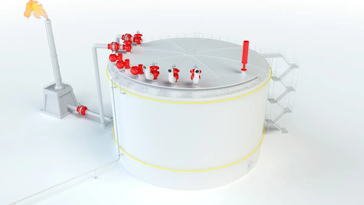
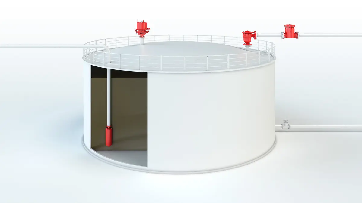
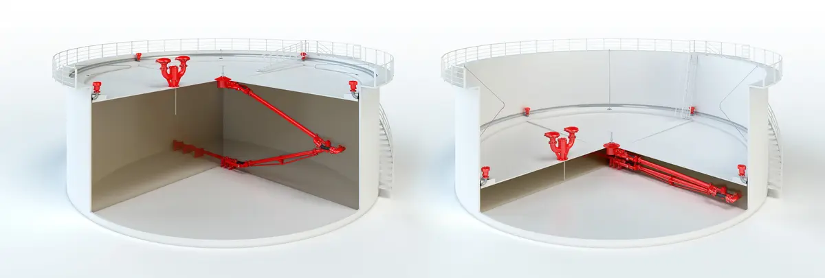
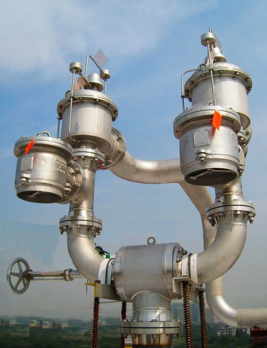
PROTEGO® WV/T Change-Over Valves are mainly used together with other valves or devices (e.g., PROTEGO® Flame Arresters Flame arrester Device fitted to the opening of an enclosure, or to the connecting pipe work of a system of enclosures, and whose intended function is to allow flow but prevent the transmission of a flame. ) on cryogenic storage tanks and on tanks in process plants in the chemical, petrochemical, and pharmaceutical industries. They increase the operational safety of the equipment Equipment Machines, appliances, fixed or mobile devices, control parts and accessories, and warning and prevention systems, whether separate or combined, intended for the generation, transfer, storage, measurement, control, and conversion of energy, and for the processing of materials, which have their own potential source of ignition and may cause an explosion. to be protected, as each valve or device Device A device is a pipe component that influences the media flow by opening, closing, or partially shutting off the flow channel or by dividing or mixing the media flow. can be checked, maintained, or repaired without interrupting plant operation.
Ensuring Performance Even with Large Temperature Differences
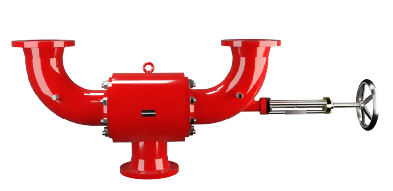
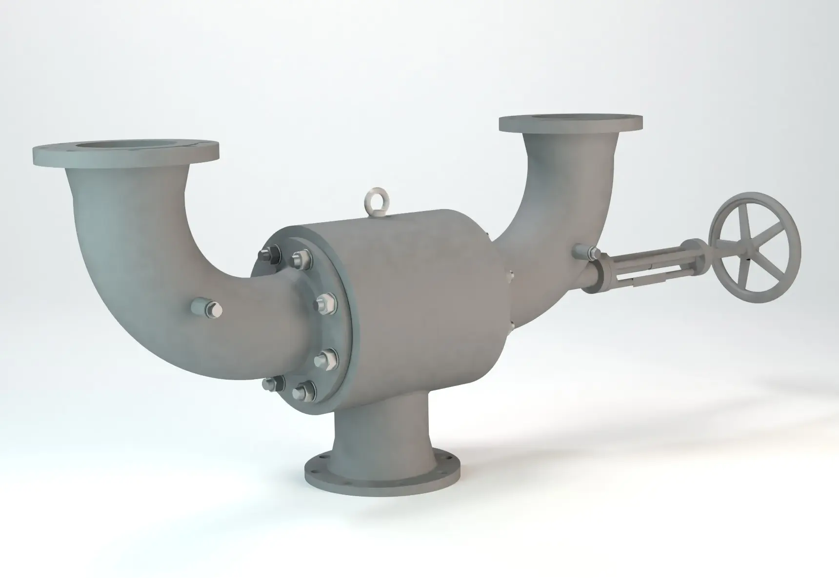
The valves mainly consist of the housing Housing A housing is a solid shell, which surrounds a content, either protecting the content from external influences, or protecting the environment from the content. (1) with flange connections DN 1 and two lateral connection elbows (3, 4) with flange connections DN 2 and the valve disc (2). If necessary, it is possible to off-set and turn the connection elbows. The valve seats (9, 10) are replaceable. The valve disc with metallic sealing surface is movable on the valve spindle (6). This ensures good contact pressure Pressure (gauge pressure) Pressure for which the value is equal to the algebraic difference between the absolute pressure and the atmospheric pressure. with the valve seats (9, 10) even with high temperature differences. The sealing between the valve disc and valve spindle is done by an O-ring O-ring O-rings are ring-shaped gaskets with a round, o-shaped cross section . The valve spindle is guided by bushings and sealed to the outside by an adjustable sealing set (7).
Flexible Operating Position with Change-Over Valve
The Change-Over Valves allows the operator to block one valve or device at a time by operating the hand wheel (8). In normal operation, the valve disc (2) is in middle position and the gas/liquid flows through both connection elbows. By turning the hand wheel as far as it will go, one of the connecting elbows (3 or 4) is closed while the other one remains open. The actual position of the valve disc is indicated by the position indicator (5) on the valve spindle. Depending on the requirements, the position of the change-over valve Change-over valve A change-over valve is a valve in which the direction of flow can be changed by operating a handwheel. in normal operation can be in the middle or end position: Middle position, for example, is if a high capacity of relief is required through emergency relief valves Emergency venting valves Pressure relief valves for emergency venting. controlled in parallel. End position, for example, is with flame arresters that are connected in parallel and can be used or cleaned alternately.
High Operational Reliability and Excellent Performance
Due to their design and appropriately selected materials, the valves are characterized by their high functional reliability and very good flow rates. All elements are made of stainless steel. The design of the PROTEGO® WV/T Change-Over Valves allows the following connections to be made in accordance with the variable valve position or other devices with both angle or straight connections without additional fittings.
Use in Explosion-Hazard Areas
PROTEGO® WV/T Change-Over Valves are characterized by their simple design, easy handling, the option of quick replacement of components that affect the function, and by their excellent availability and operational reliability. The lapped metallic sealing surfaces ensure a high degree of tightness even in low temperature ranges. These valves are not flame-proof and do not fall within the scope of the European Explosion Explosion Abrupt oxidation or decomposition reaction producing an increase in temperature, pressure, or in both simultaneously. Protection Directive 94/9/EC, even if installed in explosive atmospheres. Based on a hazard analysis with regard to material selection and function, the valves have no potential ignition sources. This enables unrestricted use in potentially explosive areas.
Dimensions
| DN1 | 80 / 3" | 100 / 4" | 150 / 6" | 200 / 8" | 200 / 8" | 250 / 10" | 300 / 12" |
| DN2 | 80 / 3" | 100 / 4" | 150 / 6" | 150 / 6" | 200 / 8" | 250 / 10" | 300 / 12" |
| a | 780 / 30.71 | 780 / 30.71 | 960 / 37.80 | 960 / 37.80 | 1130 / 46.12 | 1450 / 57.09 | 1650 / 64.96 |
| b | 250 / 9.84 | 250 / 9.84 | 310 / 12.20 | 310 / 12.20 | 330 / 13.47 | 360 / 14.17 | 415 / 16.34 |
| c * | 303 / 11.93 | 205 / 8.07 | 285 / 11.22 | 285 / 11.22 | 367 / 14.98 | 450 / 17.72 | 525 / 20.67 |
| c ** | 323 / 12.72 | 230 / 9.06 | 317 / 12.48 | 317 / 12.48 | 407 / 16.02 | 483 / 19.01 | 571 / 22.48 |
| d | 273 / 10.75 | 273 / 10.75 | 324 / 12.76 | 324 / 12.76 | 355 / 14.49 | 457 / 17.99 | 500 / 19.68 |
| e | 250 / 9.84 | 250 / 9.84 | 250 / 9.84 | 250 / 9.84 | 400 / 16.33 | 400 / 15.75 | 500 / 19.68 |
| f | 905 / 35.63 | 905 / 35.63 | 1070 / 42.13 | 1070 / 42.13 | 1200 / 47.24 | 1530 / 60.24 | 1655 / 59.65 |
| fmin | 810 / 31.89 | 810 / 31.89 | 950 / 37.40 | 950 / 37.40 | 1080 / 42.52 | 1360 / 53.54 | 1470 / 57.87 |
| fmax | 995 / 39.17 | 995 / 39.17 | 1190 / 46.85 | 1190 / 46.85 | 1310 / 53.47 | 1695 / 66.73 | 2015 / 79.33 |
Dimensions in mm / inches
* for connection flange DIN PN16 resp. from DN 200 DIN PN 10
** for connection flange ANSI 150 lbs
Material selection
| Design | A | B |
| Housing and connection elbows | Steel | Stainless Steel |
| Valve disc | Hastelloy | Hastelloy |
| Packing | PTFE | PTFE |
| Spindle sealing | FPM | FPM |
| Handwheel | Steel | Steel |
The connection flange material must be compatible to the material of the plant component Component A component that is required for the safe operation of equipment and protective systems without performing an autonomous function itself. . Special models of change-over valves are available for specific requirements.
Flange connection type
| EN 1092-1, Form B1 or DIN 2501, Form C, PN 16 , ab DN 200 PN 10 | EN or DIN |
| ASME B16.5 CL 150 R.F. | ASME |
Other types upon request
Data Necessary for Specification
Stored mediumService temperature (°C or °F)
Operating pressure Operating pressure Operating pressure is the pressure existing at normal operating conditions within the system being protected. (bar or psi)
Tank material
Tank nozzle DN1 (mm or inches)
Tank nozzle DN2 (mm or inches)
Position of nozzle I, II or III