DE/S-IIB3
High Velocity Pressure Relief Valve deflagration- and endurance burning-proof
Caractéristiques
Fonction et description
High-Speed Pressure Relief Valve
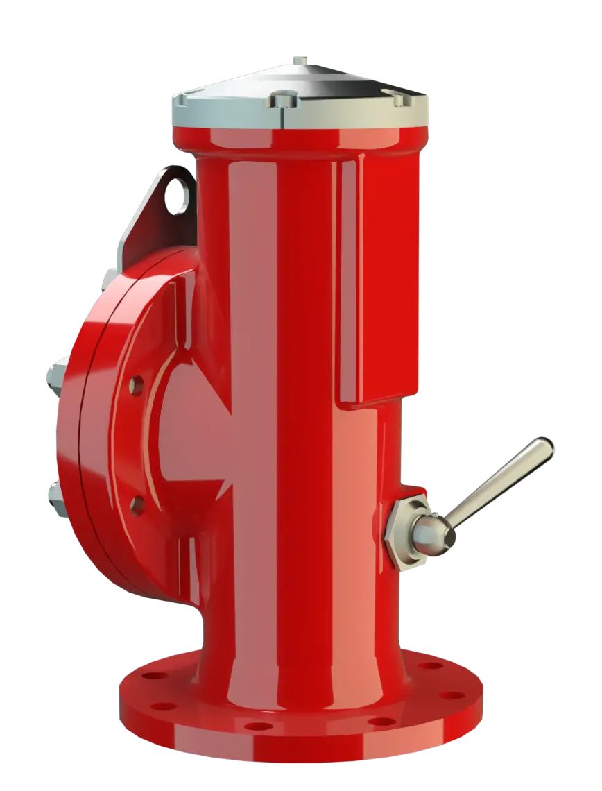
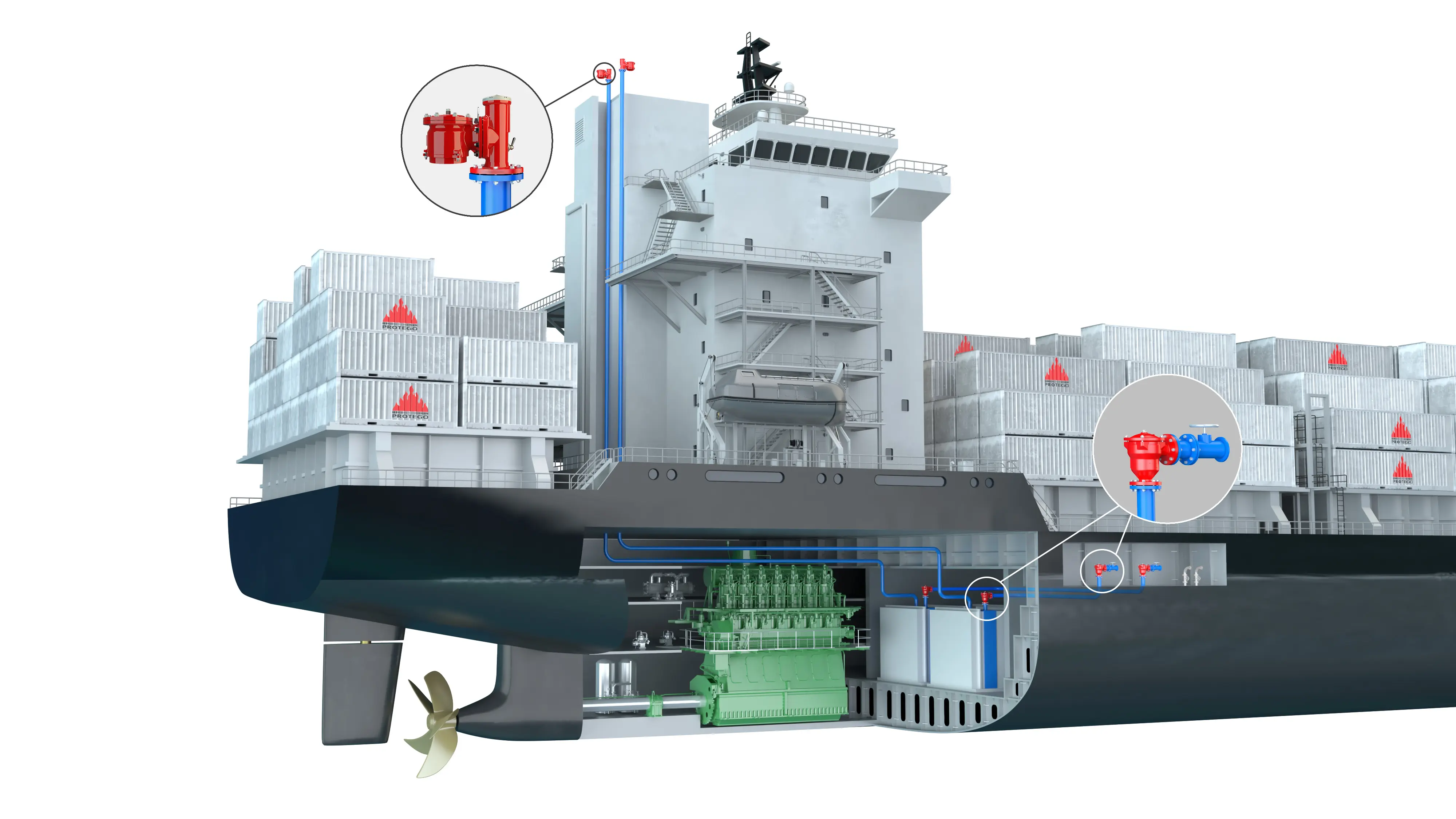
The Deflagration-Proof and Endurance-Burning-Proof PROTEGO® DE/S type device Appareil A device is a pipe component that influences the media flow by opening, closing, or partially shutting off the flow channel or by dividing or mixing the media flow. is a state of the art high velocity vent valve working on the principle of a dynamic Flame Arrester. It is primarily used as a device for flame transmission proof venting of cargo spaces and loading systems for inland waterway vessels during the loading process and on the journey. The valve offers reliable protection against excess pressure, prevents product losses almost up to the set pressure Pression de réponse Set pressure is the gauge pressure at the device inlet at which the relief device is set to start opening under service conditions. and provides protection against atmospheric deflagrations as well as endurance burning Endurance burning Stabilized burning for an unlimited time. if stabilized burning occurs. The PROTEGO® DE/S high velocity vent valve is available for substances of explosion group IIB3 (NEC group C MESG ≥ 0.65 mm).
Jump Characteristic
The valve cone (1) is kept in a closed position by a corrosion resistant permanent magnet (2). The set pressure is adjusted by the distance of the permanent magnet to its counterpart (3). Upon reaching the set pressure, the valve opens directly to a full lift Course Lift is the actual travel of the valve pallet from the main valve out of the closed position. with only a minor pressure rise (jump characteristic). The set pressure is therefore very close to the maximum allowable working pressure (MAWP) of the cargo space.

Advanced Manufacturing Technology
The tank pressure Pression de la cuve Tank pressure is the pressure within a tank. is maintained up to the set pressure with a tightness that is far superior to the conventional standard due to our state of the art manufacturing technology. This feature is ensured by valve seats made of high-quality stainless steel with an individually lapped valve cone. After the excess pressure is discharged, the valve reseats and provides a tight seal Joint A seal prevents or limits unwanted transfer of product from one container to another. Seal is used as superordinate term for all types of sealing elements. . The design of the valve cone and valve seat Siège de soupape The valve seat is a component on which the valve pallet rests when the valve is closed. produces a vertical, free jet that transports the gases far away from the discharge opening. This keeps the deck free of gas. The shape of the valve cone and valve seat promotes the drainage of rainwater when closed. A function check of the valve is easily performed with a manual lift gear (4) which returns to its initial position after actuation. A lateral flange connection, DN2, is standard for a vacuum Dépression Vacuum is the pressure in an enclosed space that is lower than the ambient pressure. valve (such as the PROTEGO® SV/E-S, see volume 7).
Dynamic Flame Arresting Safety in Overpressure Relief Valves
If the set pressure is exceeded, explosive gas/product-vapour air mixtures are released to the atmosphere. When reaching the adjusted set pressure Pression de tarage Adjusted set pressure is the pressure at which a valve opens on a test bench. , the velocity at which the mixtures exit the valve cone gap (5) (the gap between the valve seat and the alve cone) is much higher than the flame velocity. If this mixture ignites, flashback into the tank is prevented. If the mixture flow continues, the dynamic flame arresting feature prevents flashback ignition even in the case of endurance burning. As the system pressure decreases, the discharge velocity at the valve cone gap decreases also. The design ensures, that even in the closing pressure range, the valve cone closes in a timely manner keeping the discharge velocity far above the fl ame velocity and thereby preventing flashback.

Many Individual Certifications
The valve can be used up to an operating temperature Operating temperature Temperature reached when the equipment is operating under design conditions. of +60°C / 140°F and meets the requirements of ADN (European Agreement concerning the International Carriage of Dangerous Goods by Inland Waterways ) for type C ships and type N ships. EU conformity according to the currently valid ATEX directive. Approvals according to other national/international regulations on request.
Dimensions
To select the nominal size Diamètre nominal The nominal size is an alphanumeric designation of size for components in a piping system, used for reference purposes, comprising the letters DN followed by a dimensionless integer that is indirectly related to the physical size of the bore or outside diameter of the connections, expessed in millimeters. (DN), please use the flow capacity chart on the following page
| DE / S with closed lateral connection DN 2 | ||||
| DN 1 | 80 / 3" | 100 / 4" | 150 / 6" | |
| a | 515 / 20.28 | 515 / 20.28 | 515 / 20.28 | |
| b | 195 / 7.68 | 195 / 7.68 | 195 / 7.68 | |
| c | 220 / 8.66 | 220 / 8.66 | 220 / 8.66 | |
| d | 120 / 4.72 | 120 / 4.72 | 120 / 4.72 | |
| e1 | 145 / 5.71 | 145 / 5.71 | 145 / 5.71 | |
| DE / S with lateral connection for vacuum relief valve Soupape de dépression A vacuum relief valve is used to ventilate a part of the system and protects it from impermissible underpressure. DN 2 | ||||
| DN 1 | 80 / 3" | 100 / 4" | 150 / 6" | 150 / 6" |
| DN 2 | 80 / 3" | 80 / 3" | 80 / 3" | 150 / 6" |
| a | 515 / 20.28 | 515 / 20.28 | 515 / 20.28 | 515 / 20.28 |
| b | 195 / 7.68 | 195 / 7.68 | 195 / 7.68 | 195 / 7.68 |
| c | 220 / 8.66 | 220 / 8.66 | 220 / 8.66 | 220 / 8.66 |
| d | 120 / 4.72 | 120 / 4.72 | 120 / 4.72 | 120 / 4.72 |
| e2 | 100 / 3.94 | 100 / 3.94 | 100 / 3.94 | 100 / 3.94 |
Dimensions in mm / inches
Material selection
| Design | A | B | D |
| Housing | Steel | Stainless Steel | Hastelloy |
| Valve seat | Stainless Steel | Stainless Steel | Hastelloy |
| Valve cone | Stainless Steel | Stainless Steel | Hastelloy |
| Bellow | PTFE | PTFE | PTFE |
| Gasket | PTFE | PTFE | PTFE |
Special materials upon request
Selection of explosion group
| MESG | Expl. Gr. (IEC / CEN) | Gas Group (NEC) |
| ≥ 0,65 mm | IIB3 | C |
Special approvals upon request
Flange connection type
| EN 1092-1; Form B1 |
| ASME B16.5 CL 150 R.F. |
other types upon request
Design Types and Specifications
There are two different designs:* additional DN 2 information
Additional special designs upon request
Settings
| 10 kPa | 50 kPa | |
| +40 inch W.C. | +200 inch W.C. |
Higher or lower pressure settings upon request
Flow Capacity Chart
The flow capacity charts have been determined with a calibrated and TÜV certified flow capacity test rig. Volume flow V in (m³/h) and CFH refer to the standard reference conditions of air ISO 6358 (20°C, 1bar). For conversion to other densities and temperatures refer to Sec. 1: “Technical Fundamentals”.