EB-Z
Deflagration Flame Arrester, endurance burning proof, End-of-Line
Características
Função e descrição
Protection Against Atmospheric Deflagration and Endurance Burning
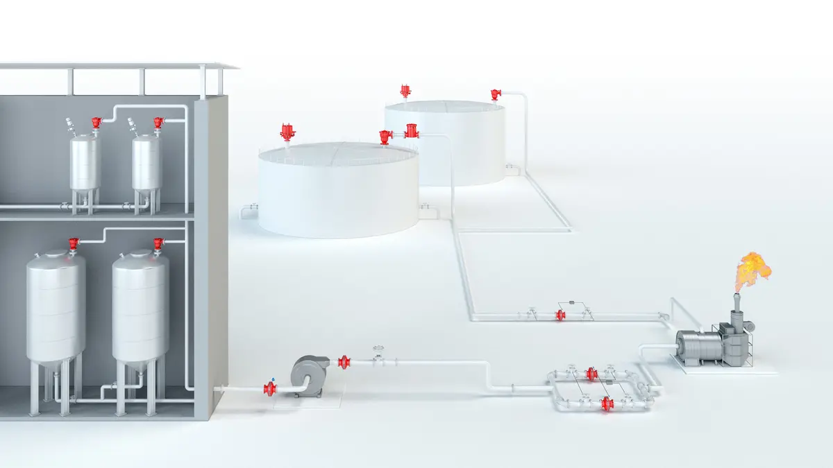
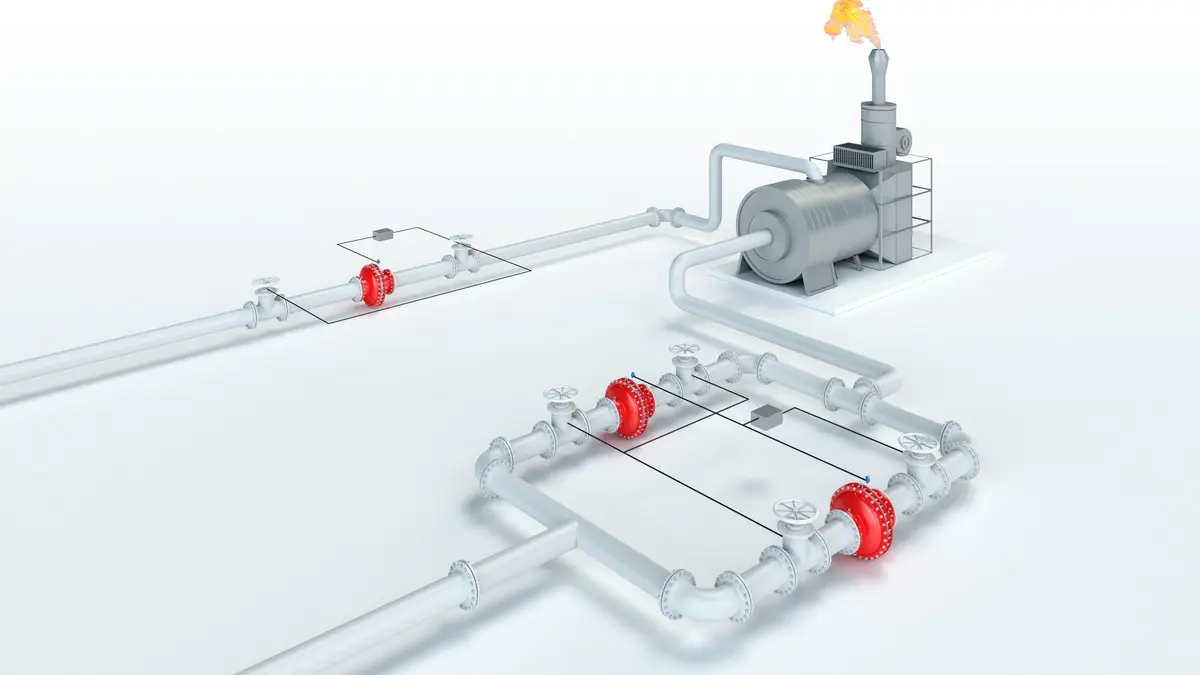
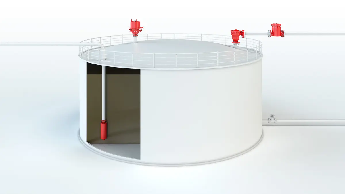
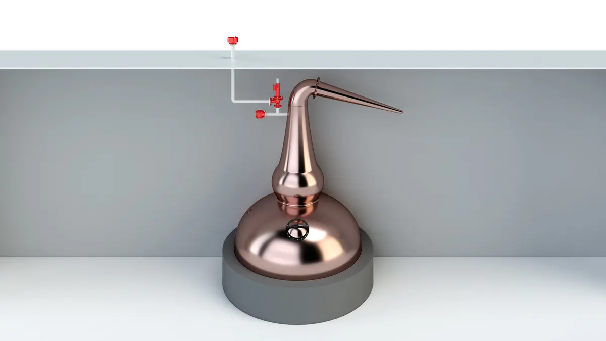
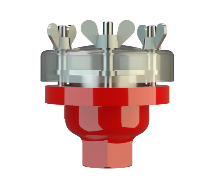
The PROTEGO® EB-Z End-of-Line Deflagration Flame Arrester Arrête-flammes antidéflagration Flame arrester designed to prevent the transmission of a deflagration. It can be an end-of-line flame arrester or an in-line flame arrester. has been successfully used to protect small vessels and process engineering apparatus which are not pressurized. The device Appareil A device is a pipe component that influences the media flow by opening, closing, or partially shutting off the flow channel or by dividing or mixing the media flow. provides protection against flame transmission through atmospheric deflagration and stabilized flames which can burn for very long time on the flame arrester element surface, so called endurance burning Endurance burning Stabilized burning for an unlimited time. . Main application area is on in- and outbreathing vent lines, with the goal to prevent flame transmission caused by endurance burning or atmospheric deflagration from propagating into the vessel Récipient Container or structural envelope in which materials are processed, treated or stored. or plant.
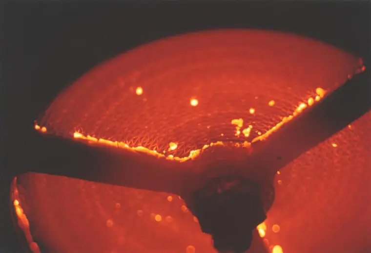
Main Component – PROTEGO® Flame Arrester Unit
The PROTEGO® EB-Z consists of a housing Corps A housing is a solid shell, which surrounds a content, either protecting the content from external influences, or protecting the environment from the content. (1), a weather hood Capot de protection contre les intempéries A weather hood is a cover to protect the internal components of a device from environmental influences. (2) and the FLAMEFILTER® (3). The weather hood is made out of acrylic glass, which will melt when impacted by flames and allow heat to dissipate to the environment. The PROTEGO® EB-Z Series End-of-Line Deflagration Flame Arrester is available for substances of explosion group IIA (NEC group D MESG > 0.90 mm)

Many Individual Certifications
The standard design can be used for operating temperatures up to +60°C / 140°F. EU conformity according to the currently valid ATEX directive. Approvals according to other national/international regulations on request.
Tabela de dimensões
To select the nominal size Diamètre nominal The nominal size is an alphanumeric designation of size for components in a piping system, used for reference purposes, comprising the letters DN followed by a dimensionless integer that is indirectly related to the physical size of the bore or outside diameter of the connections, expessed in millimeters. (DN), please use the flow capacity chart
| DN/ G, NPT | 15 / ½“ | 20 / ¾" | 25 / 1“ | 32 / 1¼“ |
| a | 87 | 87 | 114 | 114 |
| b | 93 | 93 | 98 | 98 |
| b* | 123 | 123 | 123 | 123 |
| SW | 32 | 32 | 50 | 50 |
Dimensions in mm / inches, SW= width across flats
Seleção do material
| Design | B |
| Housing | Stainless Steel |
| Weather Hood | Acrylic glass |
| FLAMEFILTER® | Stainless Steel |
Special materials upon reques
Seleção do grupo de explosão
| MESG | Expl. Gr. (IEC / CEN) | Gas Group (NEC) |
| > 0,90 mm | IIA | D |
Special approvals upon request
Tipo de conexão
| Pipe thread DIN ISO 228-1 |
| EN 1092-1; Form B1 |
| ASME B16.5 CL 150 R.F. |
other types upon request
Special designs available on request
Diagrama de vazão
Este diagrama de vazão foi determinado em uma bancada de medição de vazão calibrada e certificada pela TÜV. A vazão V em m³/h se refere ao estado técnico padrão de ar, conforme ISO 6358 (20°C, 1bar). Para conversão em outras densidades e temperaturas, veja o cap. 1: Bases técnicas.