Características
Função e descrição

In-Line Detonation Flame Arresters with Shock Wave Guide Tube Effect
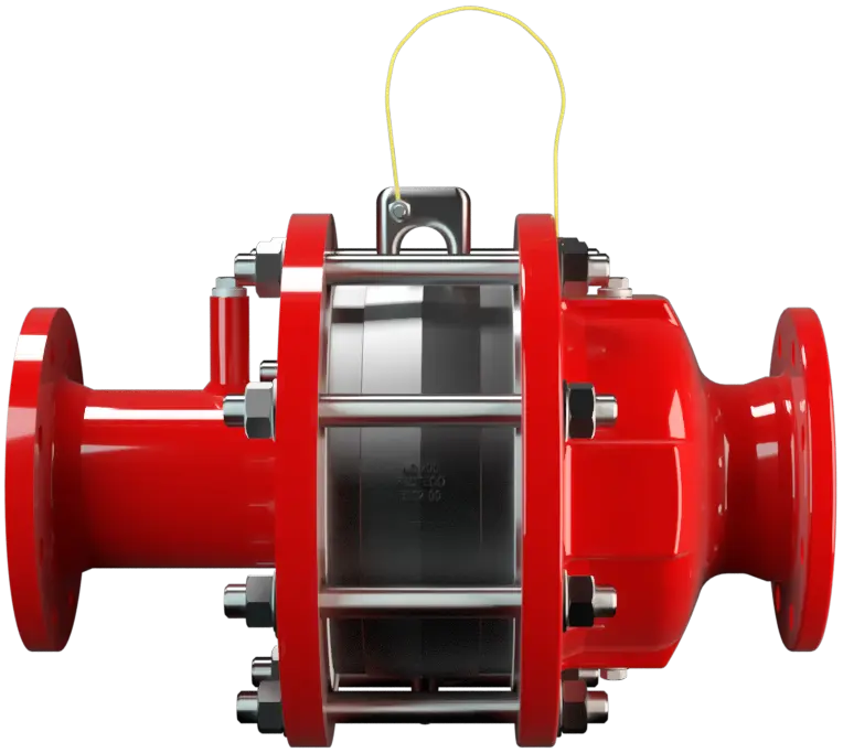
The In-Line Detonation Detonation Explosion, die sich mit Überschallgeschwindigkeit fortpflanzt, gekennzeichnet durch eine Stoßwelle. Flame Arresters Type PROTEGO® DA-SB are the newest generation of Flame Arresters. Based on flow and explosion dynamic calculations as well as decades of field tests, a product line was developed that offers minimum pressure losses with maximum safety. The Flame Arrester uses the Shock Wave Guide Tube Effect (SWGTE) to separate the flame front and shock wave. The result is an in-line detonation arrester without a classic shock absorber, which minimizes the use of FLAMEFILTER® discs.

Main Component – PROTEGO® Flame Arrester Unit
The devices are symmetrical and offer bi-directional flame arresting for deflagrations and stable detonations. The arrester essentially consists of two housing parts with an integrated shock tube (1) and the PROTEGO® Flame Arrester Unit (2) in the center. The PROTEGO® Flame Arrester Unit is modular and consists of several FLAMEFILTER® discs (3) and spacers firmly held in a FLAMEFILTER® casing. The number of FLAMEFILTER® discs and their gap size depends on the arrester‘s intended use.

Many Individual Certifications
By specifying the operating conditions, such as the temperature, pressure, explosion group, and the composition of the fluid, the optimum detonation arrester can be selected from a series of approved devices. The PROTEGO® DA-SB Flame Arresters are available for all explosion groups. The standard design can be used with an operating temperature of up to +60°C / 140°F and an absolute operating pressure up to bar / 15.9 psi. Numerous devices with special approval for higher pressures (see table 3) and higher temperatures are available upon request. EU conformity according to the currently valid ATEX directive. Approvals according to other national/international regulations on request.
Tabela de dimensões
Para selecionar a combinação dos tamanhos nominais/diâmetros nominais (NG/DN), utilize os diagramas de vazão nas páginas seguintes
outras combinações com tamanhos nominais/diâmetros nominais (NG/DN) com capacidade de fluxo melhorada sob solicitação
| NG | 200 / 8" | 300 / 12" | |
| DN | ≤100 / 4" | ≤150 / 6" | |
| a | 340 / 13.39 | 445 / 17.52 | |
| b | IIC-P1,2-X2 | - | 640 / 25.20 |
| IIC-P1,2-X3 | 500 / 19.69 | - | |
| IIC-P1,3 | - | 640 / 25.20 | |
| c | 415 / 16.34 | 570 / 22.44 |
Dimensões em mm
Seleção do material do corpo
| Design | A | B |
| Housing | Steel | Stainless Steel |
| Heating jacket (DAZ-S-(T)-H-...) | Steel | Stainless Steel |
| Gasket | PTFE | PTFE |
| Flame arrester unit | A, B | B |
O corpo também pode ser fornecido em aço, com revestimento em ECTFE.
Materiais especiais sob solicitação
Combinações de material do conjunto abafador de chamas
| Versão | A | B | C | D |
| Armação do jogo de FLAMEFILTER® | Aço | Aço inoxidável | Aço inoxidável | Hastelloy |
| FLAMEFILTER®* | Aço inoxidável | Aço inoxidável | Aço inoxidável | Hastelloy |
| Espaçadores | Aço inoxidável | Aço inoxidável | Aço inoxidável | Hastelloy |
*Special materials upon request
Seleção do grupo de explosão
| MESG | Expl. Gr. (IEC / CEN) | Gas Group (NEC) |
| < 0,50 mm | IIC | B |
Aprovações especiais sob solicitação
Seleção da pressão máx. de trabalho
| Marking | NG | 200 / 8" | 300 / 12" |
| DN | ≤100 / 4"' | ≤150 / 6" | |
| IIC-P1,2-X3 | Pmax | - | 1,2 / 17.4 |
| IIC-P1,2-X2 | Pmax | 1,2 / 17.4 | - |
| IIC-P1,3 | Pmax | - | 1,3 / 18.9 |
Pmáx. = pressão de trabalho máxima admissível em bar absoluta, pressão de trabalho mais elevada sob solicitação
in-between size up to Pmax upon request
Indicação da temperatura máx. de trabalho
| ≤ 60°C / 140°F | ≤ 180°C / 356°F | ≤ 200°C / 392°F | Tmaximum allowable operating temperature in °C |
| - | X2 | X3 | Designation |
Temperaturas de trabalho mais elevadas sob solicitação
Tipo de conexão flangeada
| EN 1092-1; Form B1 |
| ASME B16.5 CL 150 R.F. |
Outras conexões sob solicitação
Versão e especificação
There are three different designs available:Additional special arresters upon request
*Resistance thermometer (Ex i II 1/2 G Ex ia IIC T1…T6 Ga/Gb)
Diagrama de vazão
Este diagrama de vazão foi determinado em uma bancada de medição de vazão calibrada e certificada pela TÜV. A vazão V em m³/h se refere ao estado técnico padrão de ar, conforme ISO 6358 (20°C, 1bar). Para conversão em outras densidades e temperaturas, veja o cap. 1: Bases técnicas.