BE/HR-E-IIB
Deflagration Flame Arrester, endurance burning proof, End-of-Line

Características
Função e descrição
Protection Against Atmospheric Deflagration and Endurance Burning
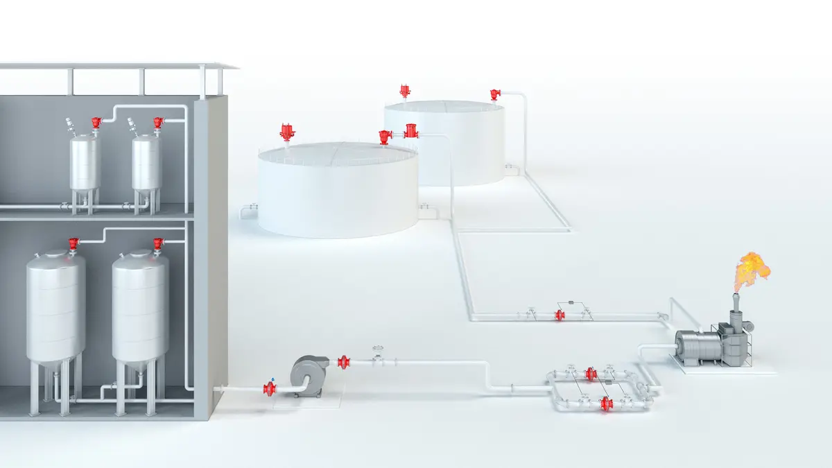
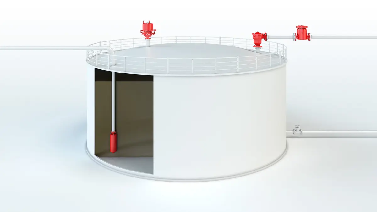
The PROTEGO® BE/HR-E End-of-Line Deflagration Flame Arrester has been specifically designed for the protection of non-pressurized systems and containers. The device is preferably installed on venting and breathing lines of non-pressurized systems and containers as well as on sea and inland tank vessels and thus prevents the entry of fire or atmospheric deflagration. The specific process of combustion reactions during stabilized burning of alcohols necessitates a constructively adapted flame arrester. The equipment provides safety against atmospheric deflagrations and endurance burning

Main Component – PROTEGO® Flame Arrester Unit
The PROTEGO® BE/HR-E-IIB consists of a housing (1), a weather hood (2) and the PROTEGO® Flame Arrester Unit (3). During normal operation, the metal weather hood is in a closed position. If a flame burns on the Flame Arrester Element surface, the fusible link (5), located in a center position, will melt and let the spring-loaded weather hood move into the open position. The PROTEGO® Flame Arrester Unit consists of two FLAMEFILTER® discs (4), which are installed in a FLAMEFILTER® casing.

For Explosion Group IIB
The PROTEGO® BE/HR-E End-of-Line Deflagration Flame Arrester is available for hydrocarbons for explosion group IIB (MESG ≥ 0,5 mm) and alcohols. The standard design can be used for operating temperatures up to +60°C / 140°F. EU conformity according to the currently valid ATEX directive. Approvals according to other national/international regulations on request. Approved according to IMO MSC/Circular 677 as well as IMO MSC.1/Circular 1324 and 1325.
Tabela de dimensões
To select the nominal size (DN), please use the flow capacity charts on the following pages
| DN | 80 / 3" | 100 / 4" |
| a | 353 / 13.90 | 353 / 13.90 |
| b | 250 / 9.84 | 250 / 9.84 |
Dimensões em mm
Dimensions for Deflagration flame arrester with heating jacket upon request
Seleção do material do corpo
| Design | B | C |
| Housing | Steel | Stainless Steel |
| Weather Hood | Steel | Stainless Steel |
| Flame arrester unit | A | A, C |
Special materials upon request
Combinações de material do conjunto abafador de chamas
| Design | A | C |
| FLAMEFILTER® cage | Stainless Steel | Stainless Steel |
| FLAMEFILTER® | Stainless Steel | Hastelloy |
| Spacer | Stainless Steel | Hatelloy |
Special materials upon request
Seleção do grupo de explosão
| MESG | Expl. Gr. (IEC / CEN) | Gas Group (NEC) |
| ≥ 0,5 mm | IIB | B |
Special approvals upon request
Tipo de conexão flangeada
| EN 1092-1; Form B1 |
| ASME B16.5 CL 150 R.F. |
other connections upon request
Diagrama de vazão
Este diagrama de vazão foi determinado em uma bancada de medição de vazão calibrada e certificada pela TÜV. A vazão V em m³/h se refere ao estado técnico padrão de ar, conforme ISO 6358 (20°C, 1bar). Para conversão em outras densidades e temperaturas, veja o cap. 1: Bases técnicas.