FA-CN-IIC
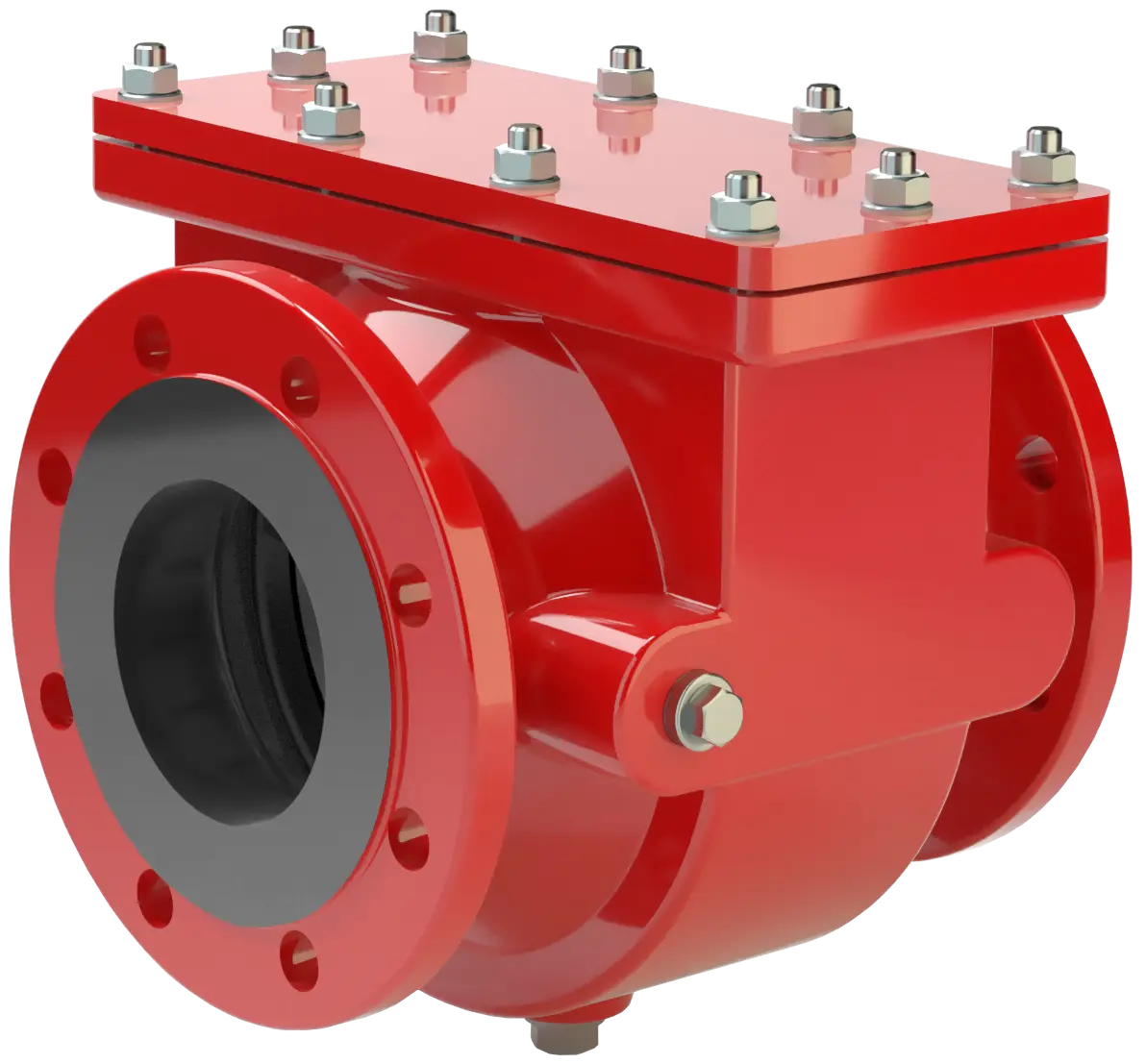
In-Line Deflagration Flame Arrester for hydrogen/air-mixtures, concentric design, bidirectional
Características
Función y descripción
Compact and Maintenance-Friendly Design
The PROTEGO® FA-CN In-Line Deflagration Flame Arrester Deflagration flame arrester Flame arrester designed to prevent the transmission of a deflagration. It can be an end-of-line flame arrester or an in-line flame arrester. is a compact design utilizing an easy access cover for easy maintenance Maintenance Combination of all technical and administrative actions, including supervision actions, intended to maintain or restore a unit in working order. . The special PROTEGO® FA-CN-IIC version was developed for hydrogen applications (group IIC vapors – NEC group B). The device Device A device is a pipe component that influences the media flow by opening, closing, or partially shutting off the flow channel or by dividing or mixing the media flow. is designed with relatively large gap widths – related to IIC – which causes minimum pressure Pressure (gauge pressure) Pressure for which the value is equal to the algebraic difference between the absolute pressure and the atmospheric pressure. loss and allows for permeation of small liquid droplets or particles.

Main Component – PROTEGO® Flame Arrester Unit
The PROTEGO® Flame Arrester Unit PROTEGO® flame arrester unit The PROTEGO® flame arrester unit is the main component of a flame arrester. It prevents flame propagation. can be removed and cleaned in just a few simple steps having to disassemble the pipe. When installing the Deflagration Flame Arrester, make sure that the distance between potential ignition sources and thelocation of the installed device does not exceed the L/D ratio (pipe length/ pipe diameter) for which the device was approved (see table 4). The Deflagration Flame Arrester is symmetrical and offers bidirectional flame transmission protection. The device consists of the housing Housing A housing is a solid shell, which surrounds a content, either protecting the content from external influences, or protecting the environment from the content. (1) with an easy access cover (3) and the PROTEGO® Flame Arrester Unit (2) in the center. The PROTEGO® Flame Arrester Unit is modular and consists of several FLAMEFILTER® discs (3) and spacers firmly held in a FLAMEFILTER® casing FLAMEFILTER® cage The FLAMEFILTER® cage is a housing for a FLAMEFILTER® set. .

For Explosion Group IIC
Specifying the operating conditions, such as the temperature, pressure, explosion Explosion Abrupt oxidation or decomposition reaction producing an increase in temperature, pressure, or in both simultaneously. group, and the composition of the fluid, enables PROTEGO® to select the best Deflagration Flame Arrester for your application. The versions of PROTEGO® FA-CN-IIC Flame Arrester Flame arrester Device fitted to the opening of an enclosure, or to the connecting pipe work of a system of enclosures, and whose intended function is to allow flow but prevent the transmission of a flame. protect against deflagrations of fuel/air mixtures of explosion Explosion Abrupt oxidation or decomposition reaction producing an increase in temperature, pressure, or in both simultaneously. group IIC (NEC B). FA-CN devices for substances of explosion Explosion Abrupt oxidation or decomposition reaction producing an increase in temperature, pressure, or in both simultaneously. groups IIA1, IIA, and IIB3 (NEC D and C (MESG ≥ 0.65 mm) are shown on separate pages. The standard design can be used with an operating temperature Operating temperature Temperature reached when the equipment is operating under design conditions. of up to +60°C / 140°F and an absolute operating pressure Operating pressure Operating pressure is the pressure existing at normal operating conditions within the system being protected. up to 1.1 bar / 15.9 psi.

Many Individual Certifications
EU conformity according to the currently valid ATEX directive. Approvals according to other national/international regulations on request.
Dimensiones
To select the nominal size Nominal size The nominal size is an alphanumeric designation of size for components in a piping system, used for reference purposes, comprising the letters DN followed by a dimensionless integer that is indirectly related to the physical size of the bore or outside diameter of the connections, expessed in millimeters. (DN), use the flow capacity charts on the following pages
| DN | 40 / 1½“ | 50 / 2“ | 65 / 2½“ | 80 / 3“ | 100 / 4“ | 125 / 5“ | 150 / 6“ | 200 / 8" | 250 / 10" | 300 / 12" |
| a | 210 / 8.27 | 215 / 8.46 | 235 / 9.25 | 240 / 9.45 | 265 / 10.43 | 305 / 12.01 | 310 / 12.20 | 300 / 11.81 | 320 / 12.60 | 350 / 13.78 |
| b | 105 / 4.13 | 105 / 4.13 | 132 / 5.2 | 132 / 5.2 | 150 / 5.91 | 197 / 7.75 | 197 / 7.75 | 220 / 8.66 | 260 / 10.24 | 295 / 11.61 |
| c | 200 / 7.87 | 200 / 7.87 | 260 / 10.24 | 260 / 10.24 | 308 / 12.13 | 415 / 16.34 | 415 / 16.34 | 446 / 17.56 | 520 / 20.47 | 600 / 23.62 |
| d | 130 / 5.12 | 130 / 5.12 | 185 / 7.28 | 185 / 7.28 | 220 / 8.66 | 310 / 12.20 | 310 / 12.20 | 355 / 13.98 | 420 / 16.54 | 490 / 19.29 |
Dimensiones en mm / pulgadas
Selección de materiales
| Design | A | B |
| Housing | Steel | Stainless Steel |
| Cover | Steel | Stainless Steel |
| Gasket | PTFE | PTFE |
| Flame arrester unit Flame arrester unit Flame arrester casing with FLAMEFILTER® set. | Stainless Steel | Stainless Steel |
Special materials upon request
Selección del grupo de explosión
| MESG | Expl. Gr. (IEC / CEN) | Gas Group (NEC) |
| < 0,50 mm | IIC | B |
Special approvals upon request
Selección de la máxima presión de operación
| DN | 40 / 1½" | 50 / 2" | 65 / 2½" | 80 / 3" | 100 / 4" | 125 / 5" | 150 / 6" | 200 / 8'' | 250 / 10'' | 300 / 12'' |
| Pmax | 1,1 / 15.9 | 1,1 / 15.9 | 1,1 / 15.9 | 1,1 / 15.9 | 1,1 / 15.9 | 1,1 / 15.9 | 1,1 / 15.9 | 1,1 / 15.9 | 1,1 / 15.9 | 1,1 / 15.9 |
Pmax = maximum allwowable operating pressure in bar / psi absolute, higher operating pressure upon request
Máx. radio L/D admisible
| DN | 40 / 1½" | 50 / 2" | 65 / 2½" | 80 / 3" | 100 / 4" | 125 / 5" | 150 / 6" | 200 / 8'' | 250 / 10'' | 300 / 12'' |
| (L / D)max | 30 | 30 | 10 | 10 | 10 | 20 | 20 | 10 | 10 | 5 |
| Designation | - | - | X12 | X12 | X12 | X10 | X10 | X12 | X12 | X13 |
Tipo de bridas de conexión
| EN 1092-1; Form B1 |
| ASME B16.5 CL 150 R.F. |
other connections upon request
Modelo y especificación
There are three different designs:Additional special devices available upon request
*Resistance thermometer for device group II, category (1) 2 (GII cat. (1) 2)
Diagrama de flujo volumétrico
Los diagramas de flujo volumétrico han sido determinados con un banco de pruebas de caudal calibrado y certifi - cado por TÜV. El flujo volumétrico V. en [m³/h] y el CFH se refi eren a las condiciones estándar de referencia de aire según ISO 6358 (20°C, 1bar). La conversión a otras densidades y temperaturas están referidas en el Vol. 1: “Fundamentos Técnicos”.