Características
Función y descripción
In- and Out-Breathing – for use with Aggressive Products
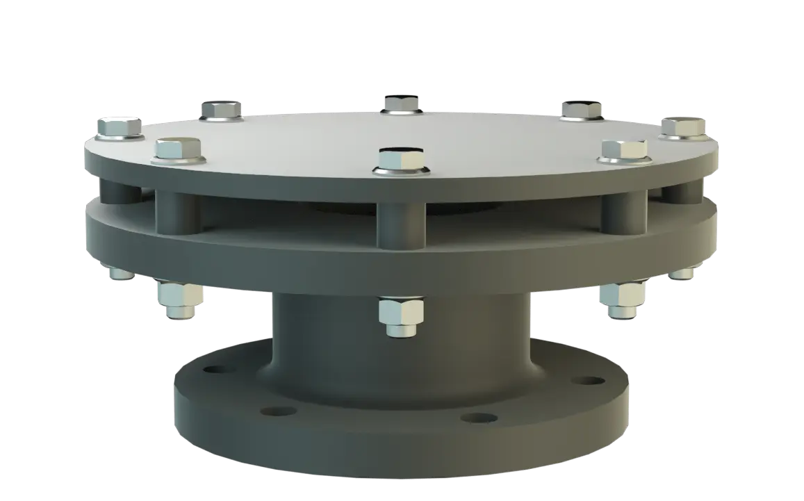
The E/KS vent cap Capot de ventilation et d'aération End-of-line device for free out-breathing and in-breathing of plant components. This device can be flame transmission-proof. allows vessels which are not pressurize to vent. The vent cap is made out of plastic and is the best solution in applications with aggressive media. This E/KS vent cap prevents rain and dirt from entering the vent line. The device Appareil A device is a pipe component that influences the media flow by opening, closing, or partially shutting off the flow channel or by dividing or mixing the media flow. is not flame transmission proof.
Protective Cover for Preventing Flame Transmission
It is often used in combination with Detonation Flame Arresters, when those are used in vent lines, installed at a position which creates a long run up distance from the end of the vent line to prevent endurance burning Endurance burning Stabilized burning for an unlimited time. . The E/KS vent cap will then be installed at the end of that vent line to prevent particles or rain from entering the line. The vent caps main components are a housing Corps A housing is a solid shell, which surrounds a content, either protecting the content from external influences, or protecting the environment from the content. (1), a weather hood Capot de protection contre les intempéries A weather hood is a cover to protect the internal components of a device from environmental influences. (2) and spacers (3).
Dimensiones
To select the nominal size Diamètre nominal The nominal size is an alphanumeric designation of size for components in a piping system, used for reference purposes, comprising the letters DN followed by a dimensionless integer that is indirectly related to the physical size of the bore or outside diameter of the connections, expessed in millimeters. (DN), please use the flow capacity charts on the following pages
| DN | 50 / 2" | 80 / 3" | 100 / 4" | 150 / 6" | 200 / 8" |
| a | 135 / 5.31 | 140 / 5.51 | 145 / 5.71 | 195 / 7.68 | 200 / 7.87 |
| b | 170 / 6.69 | 230 / 9.06 | 300 / 11.81 | 375 / 14.76 | 450 / 17.72 |
Dimensiones en mm / pulgadas
Selección de materiales
| Design | A | B | C |
| Housing | PE | PP | PVDF |
| Weather hood | PE | PP | PVDF |
Special materials upon request
Tipo de bridas de conexión
| EN 1092-1; Form B1 |
| ASME B16.5 CL 150 R.F. |
other types upon request
Modelo y especificación
Following designs are available:Special designs available on request
Diagrama de flujo volumétrico
Los diagramas de flujo volumétrico han sido determinados con un banco de pruebas de caudal calibrado y certifi - cado por TÜV. El flujo volumétrico V. en [m³/h] y el CFH se refi eren a las condiciones estándar de referencia de aire según ISO 6358 (20°C, 1bar). La conversión a otras densidades y temperaturas están referidas en el Vol. 1: “Fundamentos Técnicos”.