BR/TS-80-IIB3
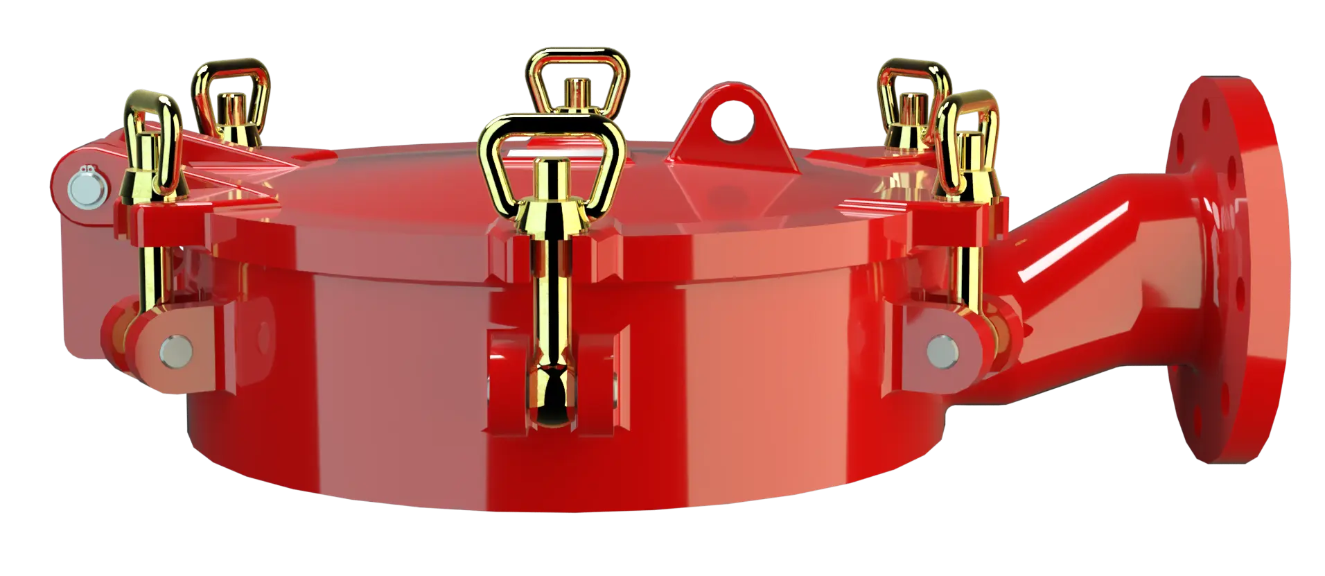
Detonation Flame Arrester for tank ships and containers
Características
Función y descripción
Protection of Tanker Ships and Containers
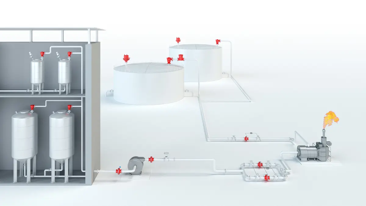
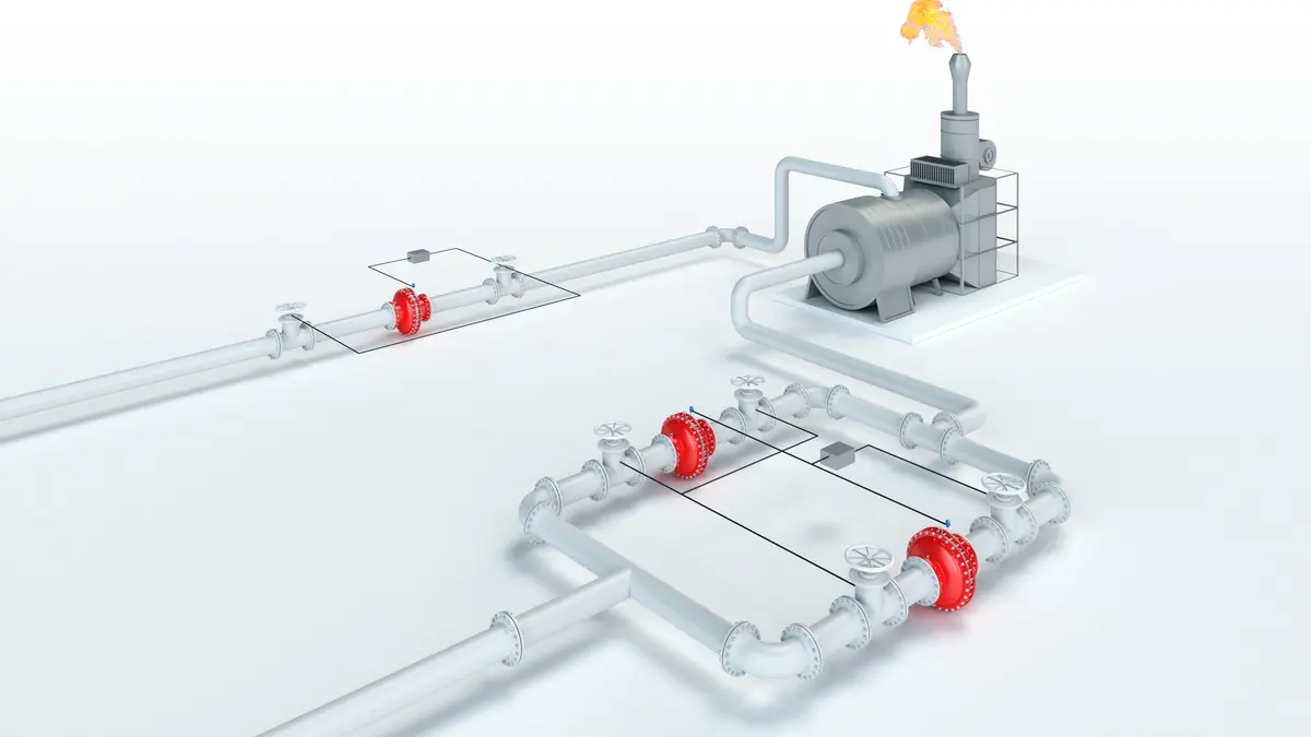
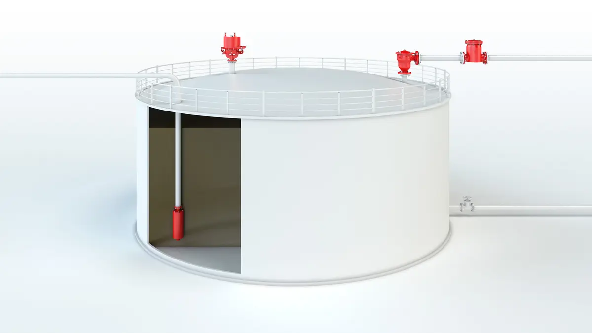
The PROTEGO® BR/TS-80-IIB3 Detonation Detonation Explosion propagating at supersonic velocity and characterized by a shock wave. Flame Arrester Flame arrester Device fitted to the opening of an enclosure, or to the connecting pipe work of a system of enclosures, and whose intended function is to allow flow but prevent the transmission of a flame. was developed for protecting tankships but can also be used for containers. These devices are especially used on tank ships operating on inland waterways or coastal shipping. The device Device A device is a pipe component that influences the media flow by opening, closing, or partially shutting off the flow channel or by dividing or mixing the media flow. is installed on the tank or a pipe section connected to the tank with a nominal size Nominal size The nominal size is an alphanumeric designation of size for components in a piping system, used for reference purposes, comprising the letters DN followed by a dimensionless integer that is indirectly related to the physical size of the bore or outside diameter of the connections, expessed in millimeters. of 250 mm / 10" and connected to the vapour balancing line (DN 80 / 3"). The individual tanks connected via the vapour balancing line are technically decoupled by the detonation arresters Detonation flame arrester Flame arrester designed to prevent the transmission of a detonation. and protected.

Main Component – PROTEGO® Flame Arrester Unit
The device protects against unidirectional detonation. In particular, the arrester consists of a shock absorber Shock absorber A shock absorber is a device that reduces the kinetic energy of a detonation. (1) and the PROTEGO® Flame Arrester Unit PROTEGO® flame arrester unit The PROTEGO® flame arrester unit is the main component of a flame arrester. It prevents flame propagation. (2). The PROTEGO® Flame Arrester Unit consists of several FLAMEFILTER® discs (3) and spacers fi rmly held in a FLAMEFILTER® cage FLAMEFILTER® cage The FLAMEFILTER® cage is a housing for a FLAMEFILTER® set. (4). It is moveable and can be folded to the side for maintenance Maintenance Combination of all technical and administrative actions, including supervision actions, intended to maintain or restore a unit in working order. . The primary goal of this design is to enable the tank to be vented or supplied with air in an emergency when ice or crystallizing products clog the FLAMEFILTER®.

For Explosion Groups IIA to IIB3
The PROTEGO® BR/TS Flame Arrester is available for explosion Explosion Abrupt oxidation or decomposition reaction producing an increase in temperature, pressure, or in both simultaneously. groups IIA to IIB3 (NEC group D and C MESG ≥ 0.65 mm). The standard design is approved up to an operating temperature Operating temperature Temperature reached when the equipment is operating under design conditions. of +60°C / 140°F and an operating pressure Operating pressure Operating pressure is the pressure existing at normal operating conditions within the system being protected. up to 1.55 bar / 22.47 psi (absolute), and it meets all the conditions of the ADN* for hazardous goods transport on European Inland Waterways. EU conformity according to the currently valid ATEX directive. Approvals according to other national/international regulations on request.
Selección de materiales para la vivienda
| Design | A | B | |
| Housing Housing A housing is a solid shell, which surrounds a content, either protecting the content from external influences, or protecting the environment from the content. | Steel | Stainless Steel | |
| Cover | Steel | Stainless Steel | |
| Gasket | Tankatite | Tankatite | |
| Flame arrester unit Flame arrester unit Flame arrester casing with FLAMEFILTER® set. | A | A |
Material selection for flame arrester unit
| Design | A |
| FLAMEFILTER® cage | Stainless Steel |
| FLAMEFILTER® | Stainless Steel |
| Spacer Spacer The spacer is a component that is generally used in a PROTEGO® flame arrester as a spacer within the FLAMEFILTER® set. | Stainless Steel |
Tipo de bridas de conexión
| EN 1092-1; Form B1 |
| ASME B16.5 CL 150 R.F. |
other types upon request
Diagrama de flujo volumétrico
Los diagramas de flujo volumétrico han sido determinados con un banco de pruebas de caudal calibrado y certifi - cado por TÜV. El flujo volumétrico V. en [m³/h] y el CFH se refi eren a las condiciones estándar de referencia de aire según ISO 6358 (20°C, 1bar). La conversión a otras densidades y temperaturas están referidas en el Vol. 1: “Fundamentos Técnicos”.